This application note covers the design and optimization of a 5th order lumped element low-pass filter using the Modelithics CLR library in concert with Agilent Genesys software. A demonstration circuit was fabricated and measured using a 16-mil thick Rogers 4003 substrate. The design process began with a conventional Chebyshev implementation in Genesys using ideal inductor and capacitor models. The simulation was then refined by the addition of Modelithics CLR models and careful modeling of the transmission line connections.
DESIGN PROCESS (FILTER SYNTHESIS USING GENESYS)
Agilent Technologies Genesys software offers a powerful tool for synthesizing filters of different orders, shapes and parameters. The following steps outline the process of creating a new low-pass filter.
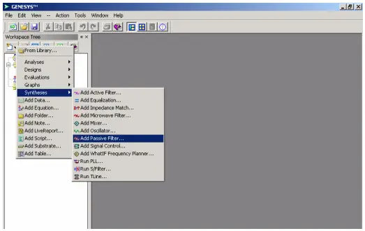
1) Select New Item > Syntheses > Add Passive Filter from the Workspace Tree as shown in Figure 1
Figure 1: Beginning the design — New Item > Syntheses > Add Passive Filter.
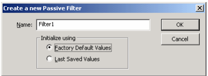
2) Enter the name of the filter in the Create a new Passive Filter box and select “Factory Default Value”. Select “OK” to continue.
Figure 2: Create a new Passive Filter box.
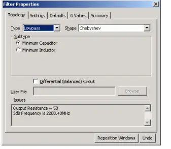
3) Select the type of filter to synthesize from the “Topology Tab”. Figure 3 shows the choice of a “Low Pass-Chebyshev -minimum Capacitor Filter”.
Figure 3: Filter Properties box showing the Topology Tab selections.
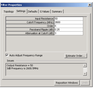
4) Select the “Setting Tab” as shown in Fig. 4. Input the parameters required for the filter design. The following values were entered for the low-pass filter.
a) Input Resistance=50
b) Cutoff Frequency (MHz) =2600
c) Order=5
d) Pass band Ripple(dB)=0.25
e) Attenuation at cutoff(dB)=3
These parameters will be different depending upon the type of filter you choose. For example, for a Band Pass Filter, the parameters include low and high cut off frequency, output resistance and resonator.
Figure 4: Filter Properties box showing the Settings Tab selections.
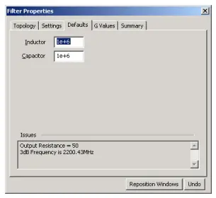
5) Select the “Defaults TAB” as shown in Fig. 5. Usually the default Q value shown below will be assigned for each inductor and capacitor. The Q can be changed if desired.
Figure 5: Filter Properties box showing the Defaults Tab selections.
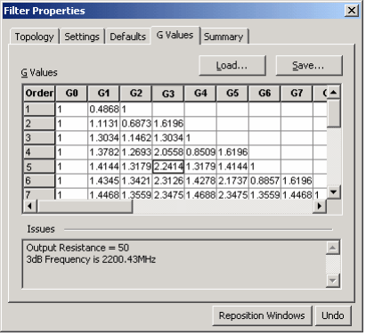
6) The synthesis tool directly computes the prototype values for the filter (“G values”) for the popular response shape. Pass Band ripple between 0 dB and 3 dB is usually chosen. The G values for the filter designed above are shown in Fig. 6.
Figure 6: G values for the low-pass filter.
7) The lumped element LPF is automatically generated along with the plots of both S21 and S11 as shown in Fig. 7 and Fig. 8.
Figure 7: Automatically generated schematic of the low-pass filter.
Figure 8: Initial S11 and S21 results using ideal elements.
SCHEMATIC CONFIGURATIONS
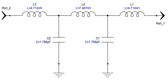
A Chebyshev filter topology was used to design a 5th order low pass filter with a cut off frequency of 2.6 GHz and 0.5 dB pass-band ripple. The ideal element values are L1=L2=4.712nH, L2=7.467nH and C=1.756pF and are shown in Fig. 9.
Figure 9: 5th order low-pass filter using ideal element values.
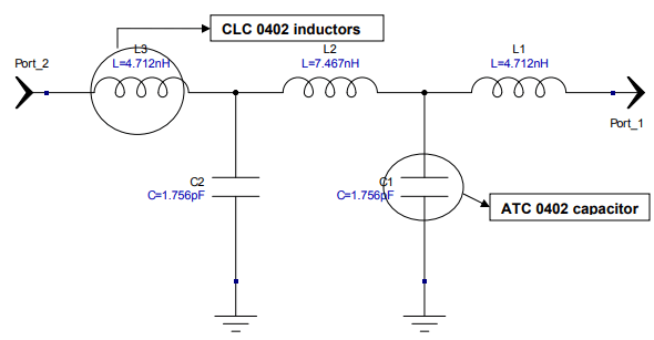
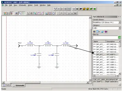
The design was implemented using Modelithics models for Coilcraft 0402 inductors and ATC 0402 capacitors as shown in Fig. 10. (In Genesys, the models can be accessed from the Part Selector A section under the current Library tab, Modelithics CLR Library as shown in the Fig. 11.
Figure 10: Low-pass filter implemented using Modelithics models for inductors and capacitors.
Figure 11: Low pass filter in Genesys. The models can be accessed under the Part Selector A section choosing Modelithics Library from the Current Library option
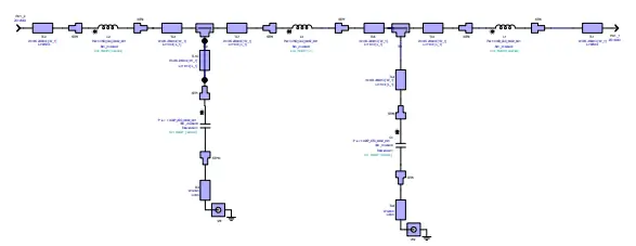
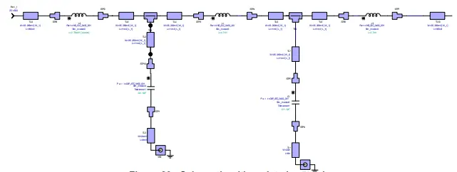
In order to further refine the simulation schematic, models for microstrip interconnects and discontinuities (e.g. Tee-junctions) are added and are shown in Fig. 12.
Figure 12: Low pass filter design implemented using Microstrip elements.
DESIGN OPTIMIZATION
In order to achieve a desired pass band ripple of 0.5 dB and 3 dB attenuation at the specified cut off frequency, the elements used in the filter design are optimized. The optimization goals are set up in Genesys as shown below
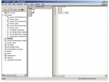
1. Enter the variables in the Equation Box. Make sure that the same variable assigned to two or more components (capacitor or inductor) be flagged .This is achieved by adding a ‘?’ after the ‘=’ sign and before the value. Fig.13 given shows the variables added to the Equation Box.
Figure 13: The Equation Box.
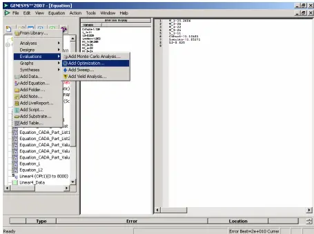
2. Select New Item > Evaluation > Add Optimization from the workspace window and double click on the Optimization Tab in the workspace tree and a window as shown in Fig. 14.
Figure 14: Select New Item > Evaluation > Add Optimization
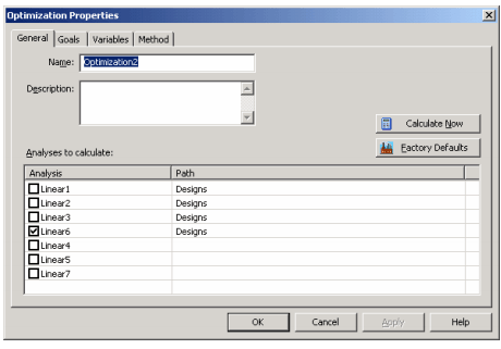
3. Enter a name and select an analysis as shown in Fig.15 shown below.
Figure 15: Optimization Properties box.
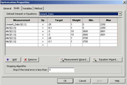
4. Select the Goal Option and set up the Optimization Goals as shown inFig. 16.
Figure 16: Optimization Goals.
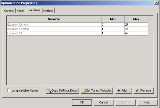
5. Select the Variable Tab and select the components (Capacitors and Inductors) to be optimized as shown inFig. 17 using the “Add” button.
Figure 17: Optimization Variables.
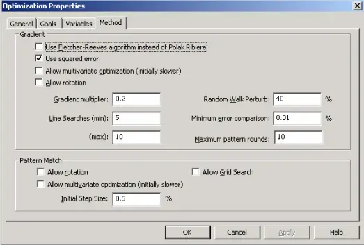
6. Set up the method of Optimization as shown in Fig. 18.
Figure 18: Optimization method selection.
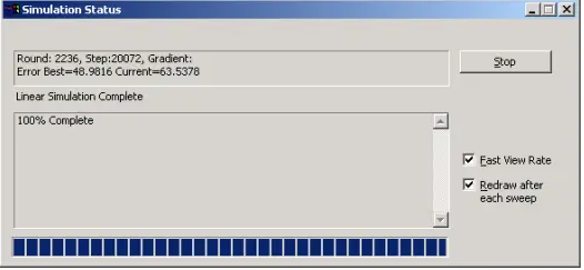
7. Select the General Tab in the Optimization Properties box and selectCalculate Now The Simulation Status window will pop up as shown in Fig. 19.
Figure 19: Simulation Status window.
The capacitors and inductors were replaced with available Modelithics components after Optimization as shown in Fig. 20. Here L1=L3=2.7nH, L2=4.7nH and C1=C2=1.5pF. Simulation has to be stopped by the user by selecting the stop tab as shown in Fig.19.
Figure 20: Schematic with updated part values.
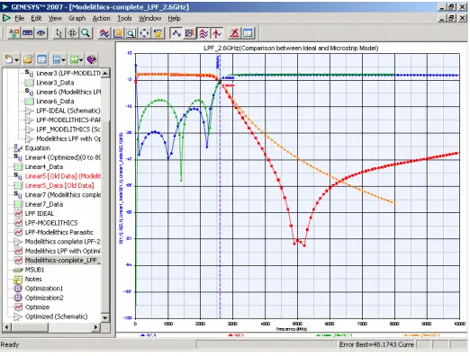
Fig. 21 shows the comparison between simulation results based on the ideal and the Modelithics models.
Figure 21: Orange and Green curves represent the ideal case and the Red and Blue curves represent the LPF after adding the microstrip elements. S21 and S11 are plotted.
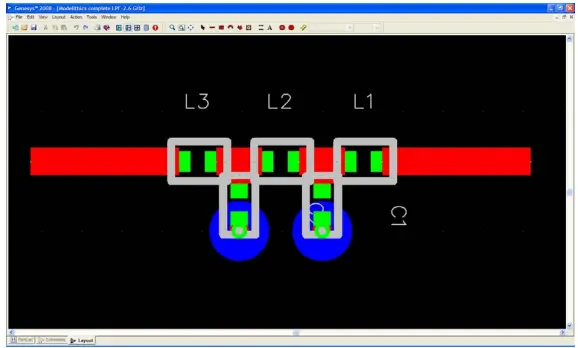
In order to view the layout of a design in Genesys right click on the Schematic, select Tab and then there will be an option for Layout. You can also select Layout Option from Designs in the New Item Tab of Workspace. The layout is shown in Fig. 22.
Figure 22: Layout of the low-pass filter in Genesys.
MEASUREMENT RESULTS
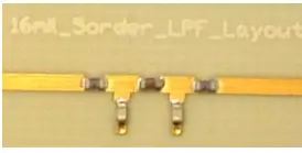
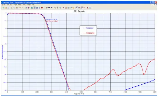
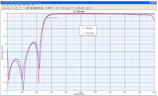
The assembled filter is shown in Figure 23. The results presented show the comparison between the ideal and Modelithics models, plotted with the measured data, including good representation of the stop-band performance. It is apparent that the design using Modelithics models agrees well with the measured data (Figure 24 and 25), and that the process presented in this application note represents an efficient microwave design flow.
Figure 23 – Assembled low-pass filter.
Figure 24: S21 Model (red) vs Measurement (blue) results from 0 to 10 Ghz.
Figure 25: S11 Model (red) vs Measurement (blue) results from 0 to 10 GHz.
MODELITHICS CHARACTERIZATION AND MODELING SERVICES
Each Modelithics Model Library contains up-to-date, measurement-based models that are fully integrated with leading electronic design automation (EDA) software. The models include complete documentation detailing the test fixtures used, measurement conditions, and model-to-measurement data comparisons. Model types include surface mount and integrated passives, diodes and multiple bipolar and field-effect transistor technologies.
Modelithics also provides rapid turn-around, RF/microwave characterization and modeling services customized to your application. Our state of the art test and measurement equipment, plus years of experience, allow us to measure a wide variety of component and system parameters, including: S-Parameters, IV characteristics, load pull, and noise characteristics. High-power testing services are also available.
ORDER A BENCHMARK FILTER KIT
Contact sales to request information on how to access the simulation files described in this note. Also, complete hardware kits consisting of fully assembled (and unassembled) versions of filters similar to that described here can also be ordered from Modelithics.
ACKNOWLEDGEMENTS
Modelithics would like to thank Mr. Reginald George for his work leading to the first draft of this application note and Ms. Sonoko Akamatsu for her prior filter design work (see Modelithics Application notes 017-020) on which this work was based. Both Mr. George and Ms. Akamatsu were formerly graduate students at the University of South Florida’s Center for Wireless and Microwave Information Systems and also were engineering interns at Modelithics in 2007 and 2005, respectively.
For more information about Modelithics Products and Services, call (813) 866-6335